Half-Wave Dipole for 11 Meters (by 56FL114, Pete)
A Simple and Certainly Working Antenna Solution
One of the easiest antennas to build is a traditional half-wave dipole. As the name suggests, the length of the antenna is about half of the wavelength of the frequency the antenna is cut for. Half-wave dipole consists of two elements that are both ¼-wavelength long.
The length of the two sides of the dipole can be calculated with the following formula: 75 ÷ frequency in MHz × V (V is the velocity factor of the material used for the two dipole elements.) The result of this calculation is the length of the ¼-wavelength element.
For example, the length of one side of a half-wave dipole calculated for frequency 27.315 MHz (CB channel 31) when using ML electrical cable is 75 ÷ 27.315 × 0.95 = 2.61 meters.
The length of the two sides of the dipole leaving from the center is 2.61 meters, and the total length of the antenna is 5.22 meters.
So the length of the ¼-wavelength wires is 2.61 meters when calculated with this formula. I will, however, suggest leaving some extra length to both sides (e.g. 10 cm) so you can trim the SWR by cutting the antenna shorter (by cutting for example 1 cm at a time from both sides).
Center Part and End Insulators
The center part of the dipole can be implemented in several ways. Many radio shops sell factory manufactured dipole center parts that have a SO-239 connector and connections for the wires with strain relief, etc. But these are quite expensive. The center part (the feed point) of the dipole is easy to make, for example, from 4-5 mm thick plexiglass.
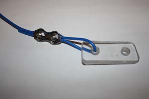
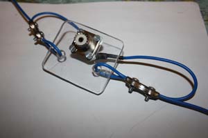
When you have a suitably sized piece of plexiglass, you will have to drill a hole in the center for the SO-239 connector and holes for the dipole wires to the sides. The dipole wires will be guided through the holes and after that bent backward and locked in place with a wire rope clamp leaving just enough wire to the ends for connecting to the SO-239 connector (look at the pictures at the bottom of this page).
The other of the two wires of the dipole is soldered to the SO-239 connector's center contact. The other is attached to the connector body, and this can be done with an Abiko ring terminal connector that is placed under the mounting screw of the SO-239 connector.
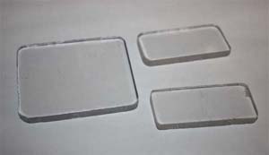
It is also a good idea to use insulators at the ends of the dipole wires. These can be made by cutting pieces from the same plexiglass and drilling holes to both ends of the piece. The other hole is for the dipole wire, and the other hole is for the rope you use to hang the dipole.
Notice also that when you measure the dipole wires, you will need to take into account the extra length that is needed to attach the wire to the insulators.
The total length of one side of the dipole is measured from the point where it is connected to the insulator at the end (i.e. the farthest point of the loop which goes through the insulator) to the mounting point at the SO-239 connector. The extra wire needed for the bend does not affect the length of the dipole.
Radiation Pattern
Below is a radiation pattern for a dipole that is hung from the ends horizontally.
A dipole can also be installed as an inverted-V. When set up as an inverted-V the center of the dipole is lifted up and the wires of the dipole are sloping downwards. In this case, the radiation pattern of the dipole is a little bit rounder when compared to a dipole that is mounted horizontally. In an inverted-V configuration, the angle between the sides of the dipole has to be at least 90°.
The dipole can, of course, also be installed as a vertical or a sloper.
Pictures
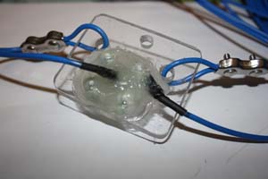
Here are some example pictures of a dipole construction from the one I built:
In the end, I covered the backside of the SO-239 connector with glue from a hot glue gun.
Will it last in Finland’s weather? That we will have to see…
Calculate the length of a dipole for another center frequency (velocity factor 0.95).
Wavelength: meters
½-wave (full dipole length): meters ( centimeters)
¼-wave (length of one side of the dipole): meters ( centimeters)


